Choosing the right Fiber Junction Box is not simply a matter of matching ports. The enclosure must protect fiber connections while fitting the installation site, cable route, and maintenance plan. A box mounted in a dusty utility room may need different protection from one exposed to rain, sunlight, or temperature changes. Small details matter.
Start by checking the number and type of fibers, required splice capacity, and whether connectors need direct access. Then consider mounting options, cable entry direction, bend-radius space, sealing, and the enclosure’s stated environmental rating. Manufacturer specifications are essential; appearance alone cannot confirm suitability. A crowded tray or sharply bent cable can complicate installation and create avoidable service issues.
Think about access later, too. Can a technician open the cover safely, identify each cable, and reach the splice tray without disturbing nearby connections? Clear labeling and enough working room can save time during repairs. Not every project needs the largest box. Oversizing may add cost and take up valuable space.
There is no universal choice. Site conditions, network design, and local installation practices all affect the decision. Check compatibility with the cable and mounting hardware, and confirm ratings with the supplier when details are unclear. One assumption can be costly. A careful review before installation is usually easier than correcting a poor fit afterward.
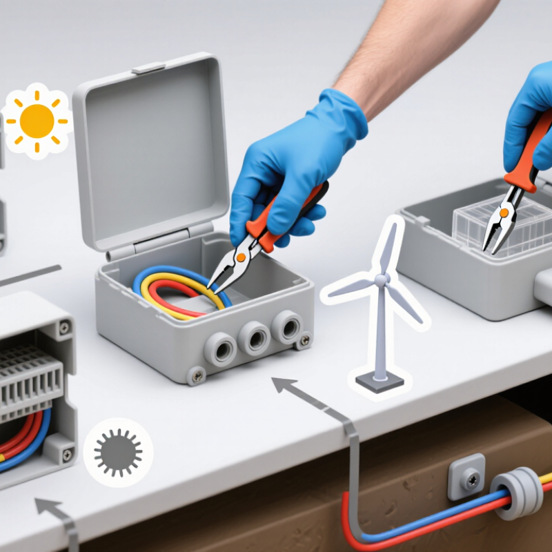
Start with the network application, not the box shape. A backbone splice point may need room for splice trays and future cable growth. A floor-level distribution point has different needs: clear labeling, easy access, and space to route fibers without tight bends. Count current connections and leave practical room for additions. That matters.
Next, examine the installation setting closely. An indoor communications room is usually sheltered, while an outdoor wall or pole may face rain, dust, temperature swings, and accidental knocks. Choose an enclosure suited to the actual exposure, and check how cables enter and seal. A rating on paper cannot compensate for a poorly fitted entry gland. Small detail, big consequence.
Consider who will maintain the box and how they will reach it. A unit installed above a crowded ceiling may be technically suitable but frustrating to service. Check mounting space, door clearance, cable bend radius, and whether labels remain readable after installation. I have seen capacity estimates feel generous until the real cable paths are laid out. Recheck the route on site; drawings often miss awkward corners. The best choice is the one that fits both the network task and the installer’s working conditions.
| Network Application | Typical Installation Setting | Suitable Box Type | Key Selection Factors | Environmental Protection | Mounting and Cable Entry | Practical Checks |
|---|---|---|---|---|---|---|
| Building backbone or floor distribution | Indoor telecom room, riser, or service corridor | Wall-mounted fiber termination or distribution box | Number of incoming and outgoing fibers; splice-tray space; connector adapter type; room for cable slack and bend-radius control | Choose an enclosure suited to the indoor location. A sealed outdoor rating is generally unnecessary in a clean, dry telecom room. | Confirm wall space, cable entry direction, gland or grommet compatibility, and access for technicians. | Check whether fibers will be spliced, connectorized, or both, and allow capacity for planned expansion. |
| Fiber-to-the-home or building access distribution | Indoor common area, building entrance, or protected outdoor access point | Access or distribution box with organized splitter and splice provision, where required | Required splitter configuration; subscriber drop count; connector layout; separation of feeder and distribution fibers | For exposed locations, select a tested enclosure rating appropriate to rain, dust, temperature, and the actual exposure. | Verify that feeder and drop cables can enter without sharp bends and that ports match the cable construction. | Check optical-loss budget and connector cleanliness; do not choose capacity solely by the number of visible ports. |
| Outdoor aerial or pole-mounted distribution | Utility pole or aerial route exposed to weather and temperature changes | Weather-resistant distribution enclosure or fiber splice closure designed for aerial use | Splice capacity; cable diameter range; strain relief; closure sealing method; resistance to ultraviolet exposure | Use an enclosure with a manufacturer-declared ingress-protection rating suitable for the site. IP65 indicates dust-tight protection and protection against water jets; it does not mean submersion-proof. | Confirm pole hardware, cable support, drip loops, entry seals, and access for installation and maintenance. | Check wind exposure, temperature range, cable pulling forces, and whether the enclosure is intended for repeated re-entry. |
| Underground feeder or distribution splice point | Handhole, underground vault, or buried duct route | Sealed fiber splice closure suitable for the specified underground conditions | Splice-tray capacity; cable port range; re-entry method; pressure or water-ingress requirements stated for the product | Select protection based on the risk of water exposure. Do not assume a general outdoor rating permits immersion or direct burial. | Check duct compatibility, cable sealing, available working space, and access for future repairs. | Confirm whether the site can flood and whether the closure is explicitly qualified for that exposure and installation method. |
| Industrial control or campus network connection | Factory floor, equipment area, or outdoor process location | Industrial fiber termination box or sealed splice enclosure | Fiber count; connector and splice arrangement; vibration resistance; temperature range; material and mounting requirements | Match the enclosure rating to dust, moisture, washdown, chemicals, and other hazards at the installation point. | Check compatibility with conduit or cable glands, available mounting surfaces, and safe separation from electrical equipment. | Review the site's environmental and electrical requirements; an ingress rating alone does not establish chemical or impact resistance. |
| Data center or equipment-room patching | Rack, cabinet, or controlled-access equipment room | Rack-mounted or cabinet-mounted fiber patch enclosure | Rack-unit space; adapter panel format; port density; cable management; front and rear access | Use an indoor enclosure appropriate to the controlled environment and equipment-room practices. | Confirm rack depth, cable routing, bend-radius guides, labeling access, and compatibility with the installation method. | Plan connector types and polarity, reserve capacity for moves and adds, and keep patch cords clear of airflow paths. |
| Building entrance or transition between outside plant and indoor cabling | Entrance room or protected transition point | Fiber termination box or splice enclosure selected for the transition design | Incoming outdoor cable construction; transition to indoor-rated cable; splice and grounding provisions where applicable | Choose protection for the actual room conditions and any risk of water entering along the cable route. | Provide secure cable anchoring, suitable entry seals, bend-radius control, and access for inspection. | Confirm applicable building and fire-safety requirements for the indoor cable segment and installation route. |
Count active fibers, spare fibers, and planned links separately. A twelve-fiber cable may need extra positions for repairs or growth. Leave practical room, not an empty maze.
Measure cable diameter and identify its indoor or outdoor rating. Check whether it is loose-tube, tight-buffered, or drop style. A sample can reveal what a drawing misses.
Match the splice tray to the fiber count and splice method. Check space for adapters and slack storage. Tight loops make repairs harder.
Wall-mounted boxes can keep cables visible in utility rooms. Rack-mounted options may organize connections beside network equipment. Measure depth and door clearance; nearby pipes can spoil the plan.
Compare the enclosure’s IP rating with expected dust and water exposure. Also consider temperature changes, UV exposure, and vibration. Ratings do not cover every site condition.
Match entry points to the direction cables arrive. Use suitable seals for each cable diameter, and protect unused openings from dust. Leave gentle service loops.
Estimate likely future connections and allow spare tray positions or entry ports where practical. Avoid filling every space now. Too much spare room can also make routing unclear.
Sketch the enclosure and label each incoming cable. Compare actual dimensions, bend space, mounting needs, and tray capacity with the specifications. I might still miss something; inspect the internal layout.
Choosing the right Fiber Junction Box starts with understanding where it will be used, such as inside a building, outdoors, or in a demanding industrial setting. Consider the network application, the number of fibers, cable types, and whether the installation requires splicing or simply connection and distribution. These details help determine the enclosure size and internal layout needed for a reliable, organized installation.
Next, match the enclosure to its environment and installation method. Review protection ratings and material suitability, then compare mounting options, accessibility, and cable-management features. A well-designed box should protect fiber connections, make installation and maintenance practical, and provide enough room for current needs as well as future expansion. Checking compatibility with the cables and components in the network helps ensure the selected enclosure is fit for purpose.

 KOCENT OPTEC