1 / 3
| Type | Single Mode (APC Polish) | Single Mode (UPC Polish) | Multi Mode (PC Polish) | |||
|---|---|---|---|---|---|---|
| Fiber Count | 8,12,24 etc. | 8,12,24 etc. | 8,12,24 etc. | |||
| Fiber Type | G652D, G657A1 etc. | G652D, G657A1 etc. | OM1, OM2, OM3, OM4, etc. | |||
| Max. Insertion Loss | Elite Low Loss | Standard | Elite Low Loss | Standard | Elite Low Loss | Standard |
| Value | ≤0.35 dB | ≤0.75 dB | ≤0.35 dB | ≤0.75 dB | ≤0.35 dB | ≤0.60 dB |
| Return Loss | ≥60 dB | ≥60 dB | NA | |||
| Durability | ≥500 times | ≥500 times | ≥500 times | |||
| Operating Temperature | -40°C ~ +80°C | -40°C ~ +80°C | -40°C ~ +80°C | |||
| Test Wavelength | 1310nm | 1310nm | 1310nm | |||
| Insert-pull test | 1000 times < 0.5 dB | |||||
| Interchange | < 0.5 dB | |||||
| Anti-tensile force | 15kgf | |||||
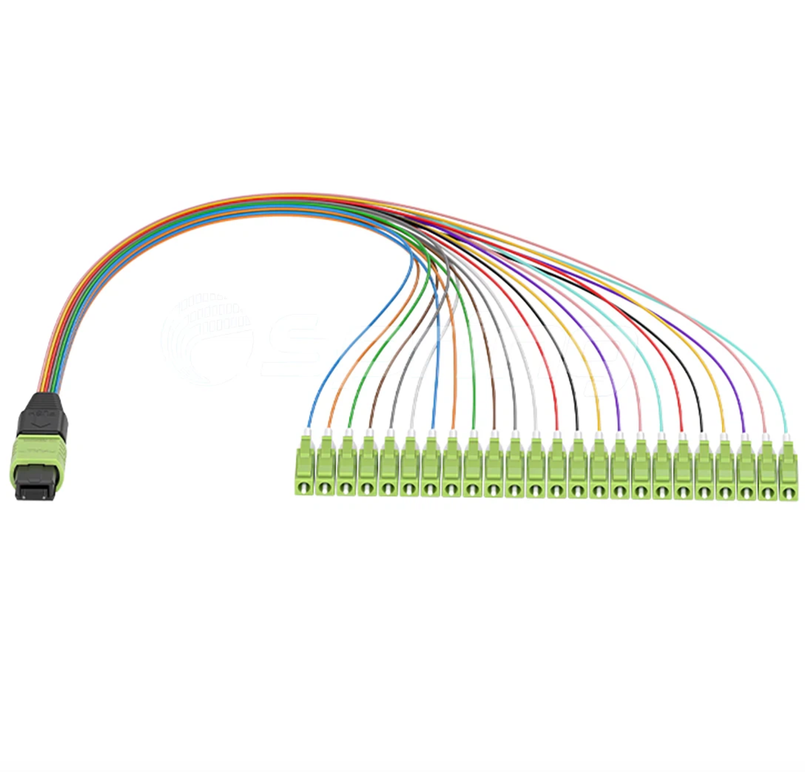
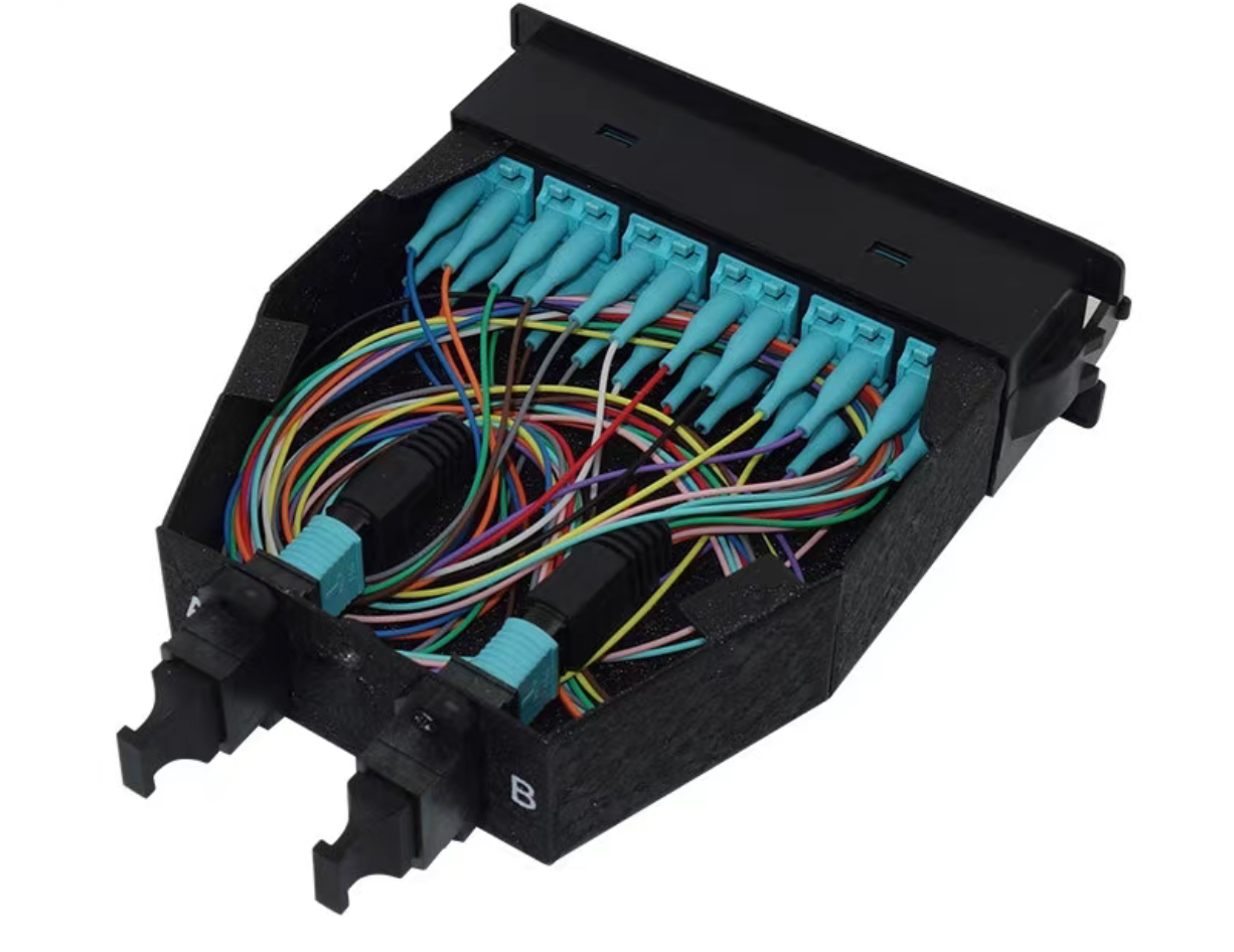
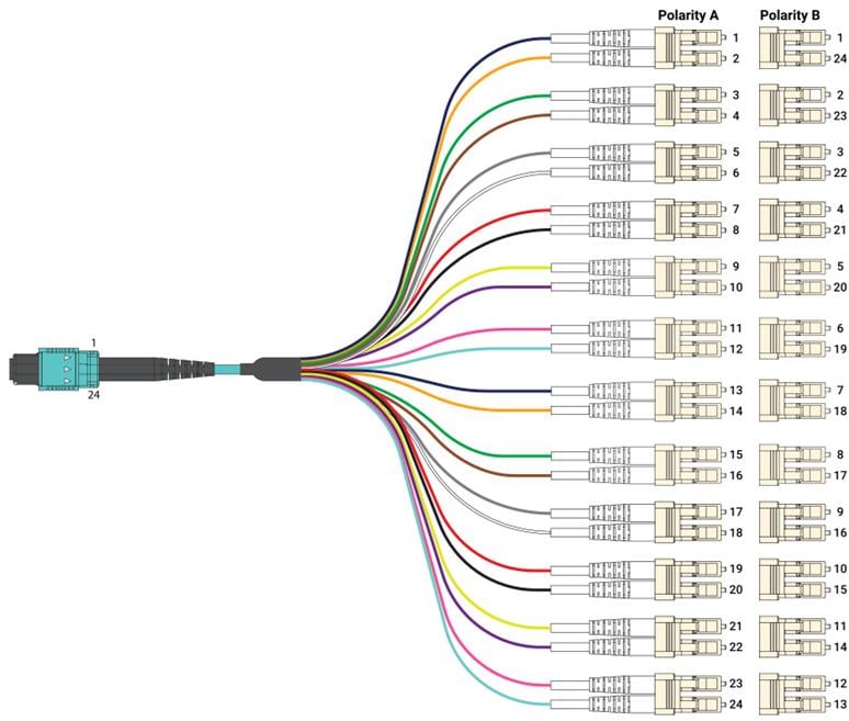
The Mapping: Pin 1 on the MPO connector links directly to LC leg 1, Pin 2 to LC leg 2, and so on.
Connector Orientation: Key-Up to Key-Down configuration.
The Mapping: Fully reversed mapping sequence. Pin 1 on the MPO connector maps to the final LC leg (Leg 12 on a 12-fiber system), while Pin 12 connects to LC leg 1.
Connector Orientation: Key-Up to Key-Up configuration.
The Mapping: Fibers are flipped sequentially in adjacent pairs. Pin 1 maps to LC leg 2, Pin 2 maps to LC leg 1, Pin 3 maps to LC leg 4, and Pin 4 maps to LC leg 3.
Connector Orientation: Key-Up to Key-Down configuration.
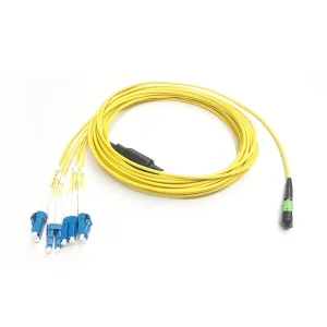
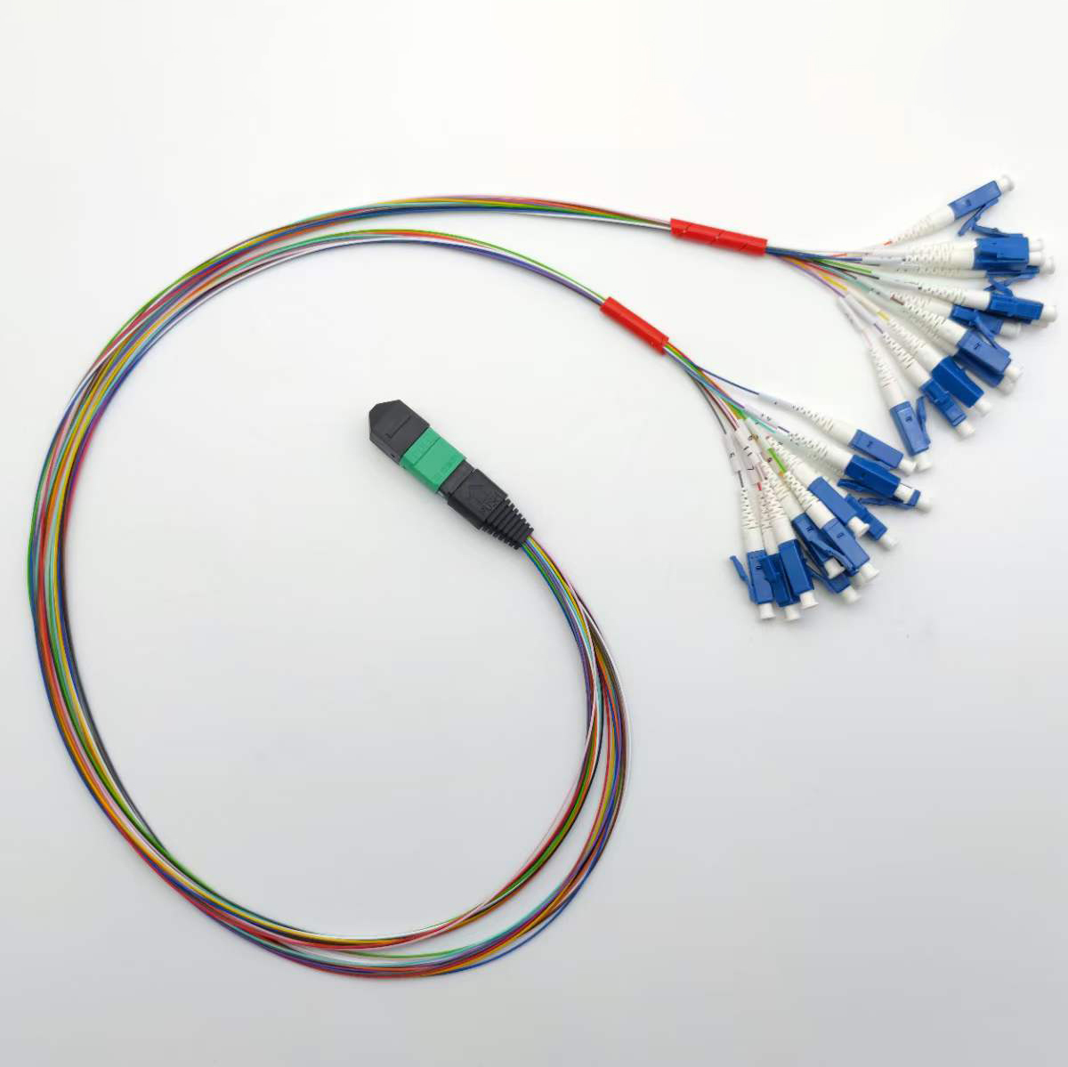
What is an MPO-LC fanout patch cord used for?
MPO-LC fanout patch cords are used to connect high-density multi-fiber MPO/MTP interfaces (such as network switches or transceivers) directly to lower-speed, discrete LC-ports, consolidating space and streamlining migration in data centers.
What makes OM5 multimode fiber different from OM3 or OM4?
OM5 fiber is designed to support Shortwavelength Division Multiplexing (SWDM) across a wavelength range of 850nm to 953nm. This allows it to carry at least four separate wavelengths on a single fiber pair, achieving 40G, 100G, and 400G transmission rates with reduced cable infrastructure.
How do I choose between Type A and Type B polarity for MPO-LC cables?
Type B (Cross-Over) is the most common choice for direct transceiver patching (e.g., QSFP+ to SFP ports) because it automatically handles the Tx/Rx reversal internally. Type A (Straight-Through) is typically used in structured backbone patch systems with cassettes where manual fiber crossing is managed at the hardware ends.
What is the difference between Elite and Standard insertion loss?
Elite (or Low Loss) connectors feature a tighter manufacturing tolerance resulting in lower signal attenuation (typically ≤0.35 dB), whereas Standard connectors provide a default margin of ≤0.75 dB (or ≤0.60 dB for multimode PC configurations).
Is OM5 fiber backwards compatible with existing networks?
Yes, OM5 fiber is fully backwards compatible with OM3 and OM4 multimode systems, allowing you to use it alongside legacy cabling setups while readying your network for future multi-wavelength upgrades.