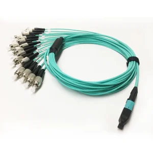
Explore our wholesale high-performance fiber optic distribution, splitting, and transceiver products engineered for critical telecommunication hubs.
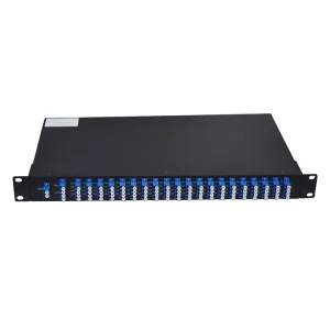
In the epoch of hyper-scale cloud computing, generative AI workloads, and pervasive 5G connectivity, the demand on fiber backbone infrastructure is experiencing exponential growth. At the physical layer of these complex data transmission systems lies the 24 Fiber Patch Panel. Positioned as the foundational interface, it bridges the gap between high-capacity trunk cables and active routing or switching equipment.
As wholesale buyers and network architects evaluate global suppliers, the selection of a 24 Fiber Patch Panel transcends purchasing a simple steel enclosure. It is a strategic procurement decision that directly impacts insertion loss, spatial efficiency, thermal performance, and optical network longevity. By facilitating structured organization of 24 distinct optical fibers within a compact 1U footprint, these panels optimize the physical topology of carrier central offices, data center cages, and enterprise telecommunication rooms.
Historically, optical distribution frames (ODF) occupied massive footprints. Modern space constraints mandate high-density configurations. The 24 Fiber Patch Panel (often configured with LC Duplex or MTP/MPO adapters) strikes the perfect balance between port accessibility and high port-count density. It enables system administrators to execute moves, adds, and changes (MACs) without disturbing adjacent lines, keeping network downtime close to absolute zero.
The global supply chain for optical fiber connectivity products is undergoing rapid diversification. No longer concentrated in single manufacturing hubs, wholesale procurement involves analyzing engineering metrics, raw material sourcing, and localized regulatory compliance. Across key markets such as North America, Europe, and Asia-Pacific, the installation of 24 Fiber Patch Panels has become a standard metric in broadband expansion initiatives.
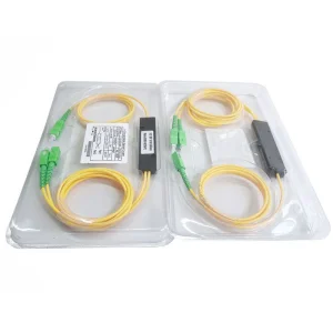
In municipal FTTH (Fiber-to-the-Home) rollouts, particularly within regions utilizing passive optical networks (PON), patch panels act as the intermediate distribution points between splitter modules and trunk lines. Industrially, automated factories and smart manufacturing plants deploy hardened, IP-rated optical distribution panels to withstand ambient particulate matter, extreme temperatures, and electromagnetic interference (EMI).
Key manufacturing benchmarks for tier-1 suppliers include compliance with international standards such as Telcordia GR-326-CORE (which governs single-mode optical connectors and jumper assemblies), IEC 61754, and ANSI/TIA-568.3-D. These frameworks govern geometric testing parameters, including fiber height, radius of curvature, and apex offset—ensuring that every patched connector maintains physical core alignment under mechanical loads.
The architecture of 24 Fiber Patch Panels has evolved from simple bulkheads to modular, multi-application chassis systems. Understanding the technology migration paths helps operators select the correct configuration for future scaling.
| Feature / Parameter | Traditional Fixed Patch Panel | High-Density Slide-Out Panel | Modular MTP/MPO Cassette Panel |
|---|---|---|---|
| Port Density | Low to Medium (24 ports in 1U/2U) | High (Up to 48 ports in 1U) | Ultra-High (Up to 96/144 ports in 1U) |
| Deployment Speed | Slow (Requires field splicing/termination) | Medium (Requires pre-terminated pigtails) | Rapid (Plug-and-play MTP backplane) |
| Modularity | Fixed adapter plate (LC/SC/ST) | Interchangeable front plates | Hot-swappable individual cassettes |
| Average Insertion Loss | 0.30 dB to 0.50 dB | 0.20 dB to 0.35 dB | Ultra-low loss versions <0.15 dB |
| Lifecycle Upgradability | Difficult; requires manual re-cabling | Moderate; slide-out tray assists upgrade | Seamless; swap cassettes from 10G to 400G |
Historically, the fiber optics industry normalized around the Base-12 architecture, where backbone cables and patch panels grouped fiber channels in multiples of 12. Consequently, a 24 Fiber Patch Panel elegantly accommodates two Base-12 links. However, with the rise of QSFP transceivers utilizing Base-8 lanes (8 fibers for 40G/100G SR4, where 4 lanes transmit and 4 lanes receive, leaving 4 fibers dark), modular patch panels must transition.
Using a 24 Fiber MTP/MPO patch panel allows operators to map three distinct 8-fiber transceivers directly through a single rack unit, eliminating dark fiber wastage and optimizing optical budget allocations. This architectural adaptability ensures that hardware deployed today can sustain migration pathways toward 200G, 400G, and 800G Ethernet platforms.
Implementing 24 Fiber Patch Panels requires a holistic approach to structured cabling. In network infrastructure design, cable management is just as critical as raw fiber speed. Improper management can lead to macro-bending losses—unseen micro-cracks in the silica core that slowly degrade signals, causing intermittent packet loss.
Integrated routing rings and protective slack spools maintain the minimum bend radius of fiber pigtails (typically 30mm for standard single-mode and 15mm for bend-insensitive G.657.A1/A2 fibers).
Modern panels utilize angled adapter alignments or internal shutters. This design prevents technicians from direct visual exposure to high-power laser signals, even when the port is unpatched.
Configured for Method A, Method B, or Method C standards, which guarantees the transmit port on one end links to the receive port on the opposite end, maintaining optical path integrity.
For carrier-grade deployments, sliding drawer mechanisms are preferred over fixed panels. They allow front access to internal splice trays, simplifying fiber fusion splicing and making individual fiber troubleshooting clean and organized. When combined with clear labeling systems, these features reduce network maintenance costs and limit human errors during high-stress troubleshooting windows.
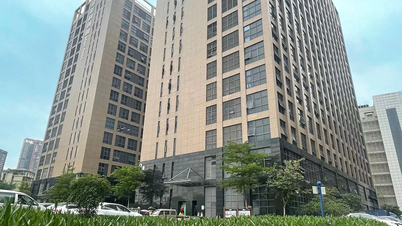
Established in 2012 in Hong Kong as a high-tech communication enterprise, KOCENT OPTEC LIMITED has grown to become one of China's premier fiber optic termination product manufacturers and solution providers. The company is dedicated to developing and manufacturing high-density fiber optic communication products, ranging from passive components to active network modules designed for carrier-grade telecommunications, complex enterprise local area networks (LANs), and high-capacity data centers.

By leveraging extensive engineering experience and a high-capacity production facility, Kocent Optec helps clients expand their technical capabilities and stay ahead of competitors. The company prioritizes close collaboration, operating not just as a vendor, but as a long-term partner in fiber optic connection solutions.
With over 13 years of specialized manufacturing experience in telecommunication fiber products, Kocent Optec adheres to strict industry standards. Using mature scientific processes, the company guarantees on-time delivery, and 100% of products are tested and inspected prior to shipment. This focus on quality assurance ensures that every 24 Fiber Patch Panel is ready for immediate deployment in mission-critical networks.
Years of commitment to customer service have earned Kocent Optec a diverse global client base. Today, the company serves operators and distributors across East Asia, Southeast Asia, the Middle East, Eastern Europe, Western Europe, Northern Europe, South America, North America, North Africa, and South Africa.
Focusing on mutually beneficial, long-term cooperation, many of Kocent Optec's OEM and ODM products have won telecom operator tenders and met demanding end-user requirements. Their products are deployed in networks managed by some of the world's leading telecom operators:
Expert technical answers to common questions about selecting, deploying, and maintaining 24 Fiber Patch Panels.
A loaded patch panel comes pre-installed with specific fiber adapters (such as LC Duplex or SC Simplex adapters) and is ready for immediate deployment. An unloaded panel features empty cutout slots (often keystones or LGX footprint cutouts), giving installers the flexibility to mix and match single-mode, multi-mode, or copper ports within a single 1U chassis. Unloaded panels are ideal for modular networks, while loaded panels simplify ordering for standard deployments.
To migrate from 10G duplex patching (typically using LC connectors) to 100G/400G parallel optics, modular patch panels use MTP/MPO cassettes. Standard LC patch panels can be upgraded by swapping the internal pigtails or front adapter cassettes with MTP/MPO-to-LC modules. This design allows operators to reuse existing rack infrastructure while upgrading the backplane backbone fiber to support high-density, multi-lane optics.
SPCC (Cold Rolled Steel) offers superior structural rigidity and resistance to bending under mechanical stress, which is essential for protecting sensitive fiber connections in data centers. It provides a stable chassis that resists sagging when fully loaded with heavy trunk cables. Aluminum is lighter and highly corrosion-resistant, but high-grade SPCC finished with electro-static powder coating offers the best balance of durability, grounding performance, and cost-efficiency for industrial racks.
The geometry of the fiber end-face (including radius of curvature, apex offset, and fiber undercut) determines the physical contact area of the mated fiber cores. Deviations in these parameters can create air gaps or core misalignment, which increases insertion loss and degrades return loss. Premium suppliers use 3D interferometer testing to verify end-face geometry, keeping average insertion loss below 0.20 dB for single-mode fiber links.
These standards define the mapping of physical fiber lanes to ensure transmit (Tx) signals on one end align with receive (Rx) ports on the other. Method A uses straight-through mapping (1-to-1 key-up to key-down), Method B uses reversed mapping (1-to-12 key-up to key-up), and Method C uses pair-flipped mapping (pairs are swapped). Mixing polarity methods in a single link can disrupt traffic, so installers must select a consistent system for all patch panels, trunk cables, and patch cords.
Installers must ensure that slack fiber is organized with protective buffer tubes and routed using minimum bend radius controls. Spliced fibers should be secured in splice trays using protective heat-shrink sleeves. Crucially, the sliding drawer mechanism must have enough cable slack at the rear to slide freely without pulling or pinching the incoming trunk cables.
The metal chassis is universal, but the fiber adapters and internal pigtails are fiber-type specific. Single-mode adapters (typically with blue LC/UPC or green LC/APC housings) utilize ceramic alignment sleeves with tight tolerances, while multi-mode adapters (typically aqua OM3/OM4 or lime-green OM5) may use phosphor bronze or ceramic sleeves. Using a single-mode patch cord with a multi-mode adapter (or vice versa) can cause high insertion loss due to mismatched core sizes (9µm for SM vs. 50µm for MM). As a result, it is best to use matching adapters for each cable type.
Angled patch panels route patch cords directly into the vertical cable managers on either side of the rack, eliminating the need for horizontal cable management panels. This setup can free up to 50% of rack space, allowing for higher density. However, angled panels require more depth clearance at the front of the rack, making flat panels a better fit for shallow cabinets or racks with front doors.
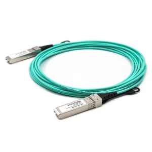
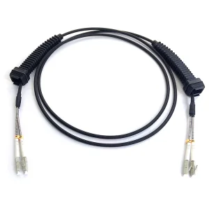
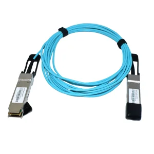
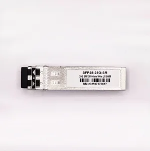
Complement your high-density patch panel deployments with premium optical transceivers, active optical cables, routers, and cleaning accessories.