Direct supply paths from certified engineering centers. Integrate high-attenuation performance and robust termination equipment into your network footprint.
Understanding attenuation stability, mechanical accuracy, and the technical migration toward high-power coherent optics.
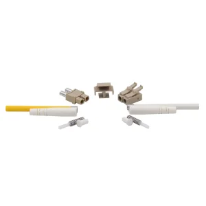
Unlike lower-grade gap-loss attenuators prone to modal distribution anomalies, carrier-grade LC attenuators utilize metal-ion doped fibers. This structural composition consistently absorbs light energy, converting excess optical power to heat without altering wavelength metrics or introducing phase noise.
As modern networks transition through 400G, 800G, and eventual 1.6T lines, fixed LC attenuators must handle elevated optical power thresholds (up to +23dBm). Our ceramic zirconia ferrules support low polarization dependent loss (PDL < 0.1dB) to secure signal integrity across long-haul transmission systems.
Achieving stable attenuation levels between 1dB to 25dB requires extremely tight physical dimensional tolerances. Our manufacturing processes utilize high-density ceramic injection molding to yield concentricity deviations below 0.5μm, preventing physical wear during repetitive matings.
A comprehensive overview detailing fixed attenuators and variable optical attenuator (VOA) profiles to assist system architects.
| Specification Parameter | Fixed LC/UPC Attenuators | Fixed LC/APC Attenuators | Variable Optical Attenuators (VOA) |
|---|---|---|---|
| Wavelength Operating Range | 1260nm to 1620nm (Dual Band) | 1260nm to 1620nm (Dual Band) | 1310nm / 1550nm / C-Band |
| Attenuation Value Range | 1dB to 25dB (1dB steps) | 1dB to 25dB (1dB steps) | 0dB to 30dB (Continuous adjustment) |
| Attenuation Tolerance | 1-10dB: ±0.5dB | 11-25dB: ±1.0dB | 1-10dB: ±0.5dB | 11-25dB: ±1.0dB | ±0.5dB across calibration curve |
| Return Loss (Min.) | ≥ 50 dB | ≥ 65 dB | ≥ 55 dB |
| Polarization Dependent Loss (PDL) | ≤ 0.1 dB | ≤ 0.1 dB | ≤ 0.15 dB |
| Maximum Input Power | 500mW (+27 dBm) | 1000mW (+30 dBm) | 300mW (+24.8 dBm) |
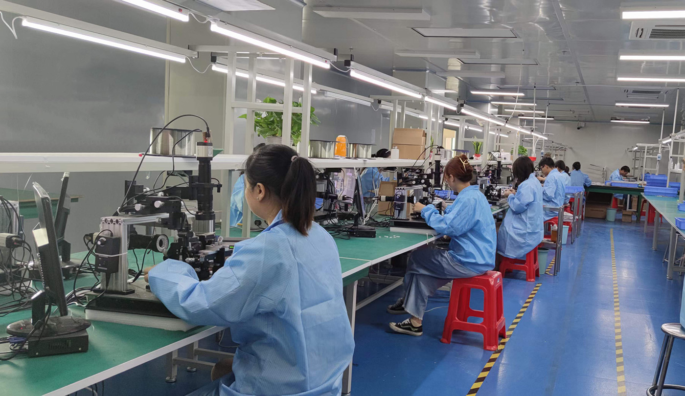
High-yield manufacturing facilities utilize automated fiber alignment, laser cleaving, and automatic fluid-doping stations. By automating standard operating procedures, we reduce human error, driving down costs and ensuring stable batch-to-batch attenuation parameters.
How system engineers integrate attenuators across hyperscale data networks, carrier fiber deployment, and next-generation mobile environments.
Optical networks operating at short distances or using highly sensitive optical receivers are susceptible to receiver saturation. Applying an LC attenuator at the receiver interface helps balance power levels to avoid hardware damage or increased bit error rates (BER).
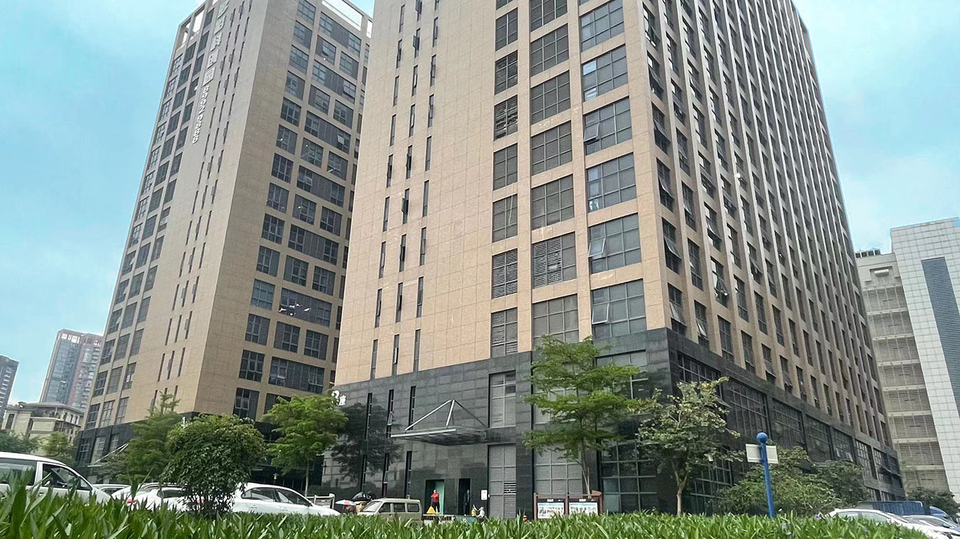
Established in 2012 in Hong Kong, Kocent Optec is a manufacturer and provider of passive and active fiber optic termination products.
Leveraging deep sector experience and structured production lines, we provide competitive solutions designed to support infrastructure rollouts. We work closely with our partners to supply robust passive interconnections alongside active transport modules.
With 13+ years of experience in manufacturing telecommunication fiber optic products, we strictly adhere to fiber optic industry standards by using mature scientific methods to deliver your products on time and ensure that 100% of products are tested and inspected before shipment.
Our OEM and ODM components are regularly used in bids and tenders for telecom operators worldwide, meeting the performance requirements of public and private operators.

Guaranteeing full mechanical, chemical, and regional regulatory compliance for critical link infrastructure.
Our LC fiber attenuators are designed and tested to conform to the requirements of Telcordia GR-910-CORE, IEC 61300, and RoHS/REACH environmental regulations. Flammability-rated polymer housings meet UL 94V-0 standards.
Every polished ceramic ferrule is inspected using 3D interferometry. Crucial metrics like apex offset, fiber height, and radius of curvature are monitored to ensure consistent physical contact over long deployment lifecycles.
With distribution nodes in Hong Kong and manufacturing centers in mainland China, we coordinate global logistics. We handle regional export customs clearance, customs documentation, and split-shipment routing.
Technical guidance regarding LC attenuator design, deployment, and factory quotes.
Doped-fiber LC attenuators use metal-ion doped fiber to absorb optical power evenly, distributing heat throughout the material. This ensures stable performance across 1310nm to 1550nm. Gap-loss attenuators rely on physical separation, which can lead to optical back-reflection and modal distribution issues.
Low return loss can cause optical reflections to bounce back into the laser cavity, generating phase noise and signal degradation in high-speed networks. We specify our LC/UPC attenuators at ≥50dB and LC/APC versions at ≥65dB to protect active transceivers.
In high-power coherent optical systems (above +20dBm), standard attenuators may degrade or fail due to heat build-up. For these applications, select attenuators with high-power zirconia ferrules and specialized doping compositions rated for higher optical power thresholds.
Ensure factory quotes specify the ferrule type (Zirconia Ceramic), attenuation tolerances, operating wavelength bands, return loss levels, and compliance standards (RoHS/REACH). Requesting 3D geometry testing reports can help verify long-term mating stability.
A full range of patch panels, transceivers, and accessories to support active opto-electronic deployments.
 KOCENT OPTEC